
The construction of the antenna took time. But it ready and it wiggly fit in my apartment.
The construction of the antenna I start with linking of the boom sections. I will remind the reader that I make the boom of three parts. Each part is a 1m long square tube (10x20x1000). For their connection, I mill 2 aluminum bricks which I put inside the tube. Outside (on both sides) I connect the tubes with a steel strip of 20 mm wide. I bought 1m long strip and cut it on 4 parts. These strips I connect to tube with 10 screws. Probably I slightly exaggerate with rigidity, but it vertical plane it doesn't oscillate at all.
The next step is the precise cutting of antenna elements. For this, I had used brick with a hole and mini vice. The hole size of the brick is equal to the tube diameter. After I improve the cut with a mini file. In my case, the precision of cutting is determined by the measurement instrument. I had used a ruler of 35 cm length with 0.5 mm precision. This is about the precision with which I made the elements of the antenna. Hopefully, I had no element longer than 35 cm, so my ruler was enough.
The next is a markup of the boom. For this, I had to use a usual roulette and this is not cool. However, it is better than to use a short ruler and put marks. Because with a small ruler you will accumulate an error quite fast. Unfortunately to the marking problem adds the drilling precision problem. Another problem is that the metal of the tube is quite thin, so I cannot make a good thread in it. For M3 I have only 1.5-2 turns. That's why it better to don't tie the screws much.
Almost all the connection elements of the antenna I print on the 3D printer. But there is a problem with printing precision. I reduce the printing speed to increase precision, but anyway I need to adjust the elements with drill and file. The problem was also that the big elements bent on my printer. Probably its program failure (not enough support), but I needed to solve this problem as well. So to adjust these elements, I heat them with soldering fun (hot air gun) and adjust. The holes in the middle of each element I drill after I insert them into connectors. For this, I also uses vice, and my self made mini drill.
The most difficult thing to make was a reflector. This took the same amount of time as to make all the rest of the antenna. I didn't think about this when I design the antenna, so I have this experience now. At the end of each element, I put black caps that are used to protect SMA connectors. With these caps, antenna looks better, and also it has a practical advantage: the humidity would not enter the tubes and so the parameters of the antenna will be more stable.
The elements of the dipole are connecter to the SMA connector of the antenna throw brass washers to prevent the creation of galvanic pair aluminum-copper. After this, I find the mass center of the antenna (method of 2 fingers) and connect there mast interface connector. The ready antenna looks like in the picture above.
TEST
So exciting moment. Well, how to measure the antenna parameters? Hopefully, I have a micro vector analyzer NanoVNA. At the moment of purchase, it costs less than 50 euro (and now even less). To correctly measure antenna parameters you should calibrate the analyzer with that cable which you will connect to the antenna. The calibration procedure is simple but necessary. There is also a program to communicate with PC. So here what I got:
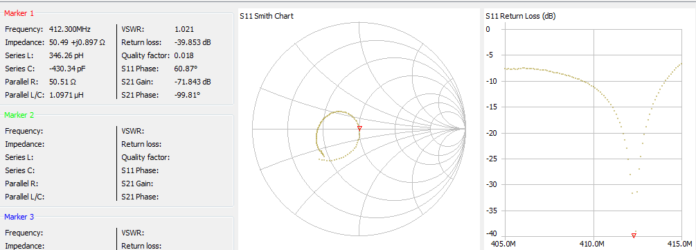
So we have VSWR=1.021 (close to the analyzer error). The minimum is on the 412.3 MHz (I miss only 2 MHz). The deepness of the minimum is -40 dB. As the preliminary test was in my room (I tied the antenna with shoelaces under my mezzanine), the result is motivating.
The next step is to move the antenna to the observatory site and to test it outside.
This is a fascinating project! I appreciate the detailed descriptions of the antenna assembly and testing process. It's impressive to see the dedication and effort going into building equipment capable of detecting signals from such distant and mysterious objects like neutron stars.