
The best article I have seen on the principles of the RTL-SDR receiver operation is described here. Here is a brief synopsis of this article. In a few simple steps, I will try to tell you how this receiver works.
Step 1. Simple demodulation
Let us assume that we have a signal  with amplitude modulation on carrier frequency
  :
:

To demodulate the signal, I will multiply it on cosine with the same frequency . Product of multiplication of two cosines is:

or in our case:

HF part (at double frequency) is cutted by the low-pass filter. Schematically it can be represented as:
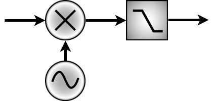
So in result we have only modulated signal  .
.
However, we have also nonzero phase  of the signal:

The result of the demodulation in general form is:

After the filtering we have  . In the worst case
  and the message is impossible to reconstruct. The solutions is to mix the signal also with shifted of 90 deg signal (with sine basically).

As sine and cosine never turns to zero at same time, so we can always demodulate the signal by taking Euclid norm for example. The schema of this demodulation device is:
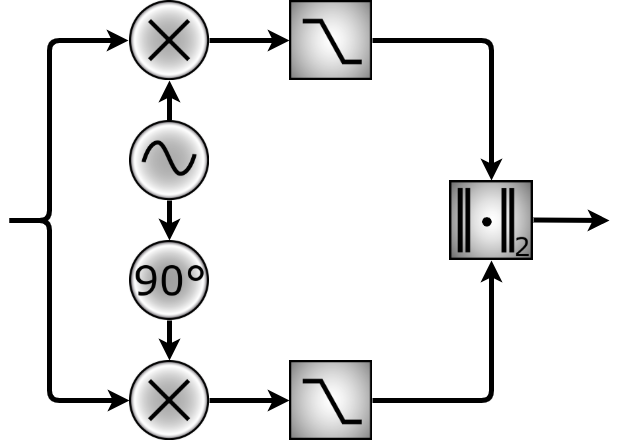
So whatever phase we have, at the output we will always get . Basically this is a lock-in amplifier. Except the amplitude, it also measures the phase. The component in phase (multiplied by cosine) is I-component and the other one (which is multiplied by sine) is quadrature Q-component.
Step 3. Superheterodyne
Except for the problem of phase, there is a problem with noise. The classical solution on the radio domain is superheterodyne. The idea is the following: first, we filter the signal at high frequency (radio frequency) and amplify it (with LNA -- low noise amplifier). Then the signal is mixed with the signal from local oscillator  . The frequency of it is slightly shifted from the frequency of the measured signal and at the output of the mixer, we have a signal on the intermediate frequency
  , which is equal to the difference of two.The signal again is filtered and amplified. If necessary the down conversion is possible with schema described in step 1.
Why not make downconversion immediately? Because the signal usually needs to be amplified. The noise of the RF amplifier is usually inversely proportional to gain. On low frequencies, the gain can as high as desired, but the noise is much larger. The compromise is to use intermediate frequency with low noise and high gain.
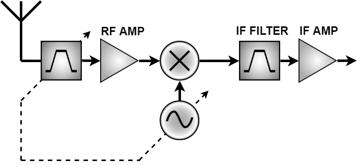
But there is some problem with image signals. In the IF bant can pass the signal at the frequencies  . That's why the input RF filter is necessary.
Step 3. RTL-SDR
This receiver uses the principles described above and contains two main chips:
- Tuner. It is basically superheterodyne
- RTL2832U measure the signal and makes some digital signal processing. It also contains a block of USB control.
The schematic of the receiver is on the picture below:
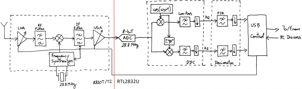
So first we have an LNA amplifier and bandpass RF filter. This filter cuts the image frequencies down to -65 dBc. Signal of the PLL frequency synthesizer mixed with the input signal. The intermediate frequency of the receiver can be from 3.57 to 4.57 MHz. The frequencies of which RTL-SDR is able to work are determined by the frequency range of the synthesizer. In the datasheet of the chip specified frequency range from 42 to 1002 MHz, but in practice, the frequencies 24 to 1766 MHz are achievable (even more with some experimental drivers).
Then the signal is filtered and amplified by the variable gain amplifier (VGA). The IF filter is more selective than RF (due to superheterodyne architecture). This filter is composed of low and high pass filters and it can be adjusted on bandwidth from 300 kHz to 8MHz. In general, the tuner have 3 gain settings: LNA, mixer, and VGA. The gain can be adjusted automatically to reach the best signal to noise ratio.
Then the signal goes to the RTL chip. There it is digitized on 28.8 MHz and processed with a digital lock-in amplifier. After a low pass filter goes downsampling because the useful signal is limited by the filter at a lower frequency. After this data goes throw FIR (finite impulse response) filter to limit the sampling on 2.56 MHz or lower. This filter determines the maximal bandwidth of the receiver.
At the output, we have an 8-bit IQ signal which is transmitted to the computer throw USB. It is quite easy to manipulate with it in GNU radio. Here is my version of an FM receiver with RTL-SDR and GNU radio.