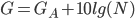
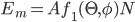
So to be able to detect pulsar in reasonable observation time, the minimum gain of the antenna should be at least 14dB at 400 MHz. I choose a linear polarization for the antenna because it is the most simple configuration.
The choice of antenna type is guided by several factors: budget and construction time, compactness, and simplicity. Basically, I need a small, light, cheap, compact antenna that can detect at least one pulsar. The ideal type for this purpose is a dish-type antenna, but it is not small. Moreover, making a dish of less than  diameter makes no sense because the Udo-Yagi antenna type will work better.
It is also essential to analyze the experience of successful pulsar hunters. The main webpage of them is Neutron Star Group. There is a list of all successful attempts of amateurs to detect a pulsar. The list is in the order of increasing the aperture of the antenna, and also, there is the same list ordered by the number of registered pulsars. What I am interested in is the detection cases with small antennas. The first antennas on the list are quite extravagant. They are a bi-square and a 3D angular reflector antenna.
This is quite motivating. That means that it's not so difficult to catch a pulsar, but there are some "nuances." Three successful reflector antennas and a bi-square were made by one person - Andrea Buti. Besides, this man has experience of work with a 4-meter dish and is likely to have extensive experience in EME (Earth-Moon-Earth) communications. This means that if you have enough experience and good electronics, that means that you can catch a pulsar on a piece of wire, but not that it is easy to detect a pulsar.
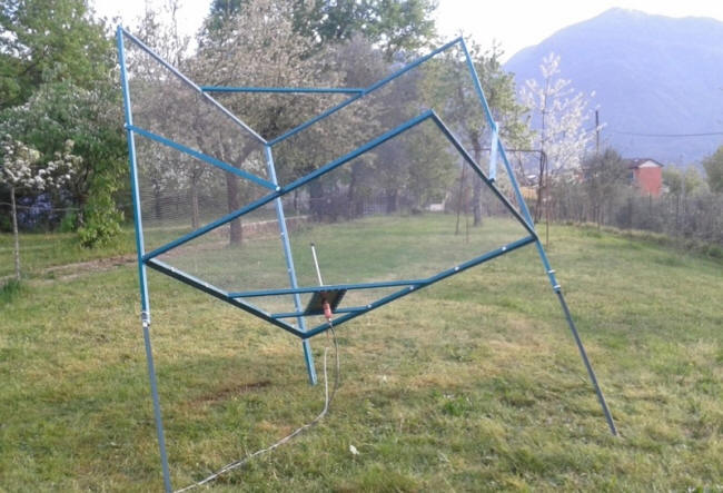
3D reflector antenna
Andrea Buti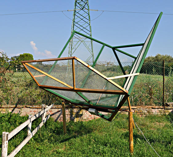
3D Reflector Antenna in
Tavolaia Observatory
I was interested in the 3D reflector antenna. It is easy to manufacture and should be cheap. The maximum gain is about 18 dB. But I'm afraid that it will be challenging to use (debugging, alignment). Another disadvantage is that increasing its area beyond a specific boundary does not increase the gain. I have not yet found any other projects using this type of long-wave antenna (70 cm for me are long waves), although there was an unsuccessful attempt to build it by one talented author. Maybe in the future, I will decide to make and to try this type of antenna, but not today.
The next type in the list is a 23x element Yagi antenna. It looks pretty artisanal, but it's more like what I would like to get as a result. The antenna is easy to understand and simple to manufacture and simulate. It is estimated to have 18.6 dB gain. But there are a few things to notice: the observation time is 4 hours, and the band is 2 MHz. That's means that you have to sacrifice both the observation time and the quality of the impulse. Second, the antenna is 5 meters (!!!) in length, and it bends like a snake. Thirdly, the author has a 3m dish at home, as well as experience of detection pulsars with it EMEs past, which again proves that if you have experience and good electronics, the antenna does not matter.
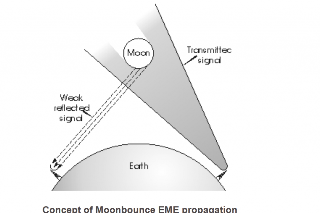
Almost all other pulsar hunters have dish antennas of different diameters, and they are radio amateurs with considerable experience. Most of them had practiced EME radio communication. Earth-Moon-Earth (EME) is a type of communication that uses the Moon as a reflective surface of the radio signal. In this way, you can set up connections in different corners of the planet (within the Moon's view). This type of radio began to appear in the '60s when cheap amplifiers with very low noise began to appear on the market. The radio amateur experience of pulsar hunters also explains the fact that antenna frequencies are in the radio amateur range (420-450 MHz) and not in a dedicated band for astronomical radio observations (406.1-410 MHz).
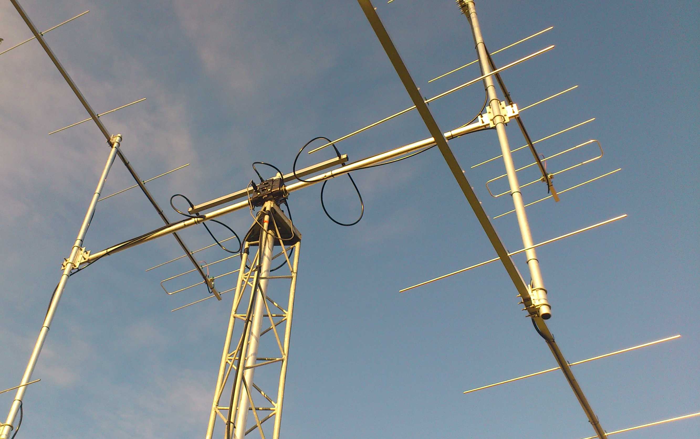
There are not many other options left on the list, but there is one I like. The use of an in-phase antenna array is standard in EME. So, there are information resources where I can get a hint in case of problems, as opposed to a 3D reflector antenna. Another advantage is that the Yagi antenna does not need debugging when it is correctly assembled. In addition, the antenna array can be made from relatively short antennas, and it is possible to achieve required gain by multiplication of their number (for me, it is easier to use and manufacture four short antennas than one long). Another advantage is the possibility to scale the array. It's to say that you can add a few more antennas to the grid and increase the gain.
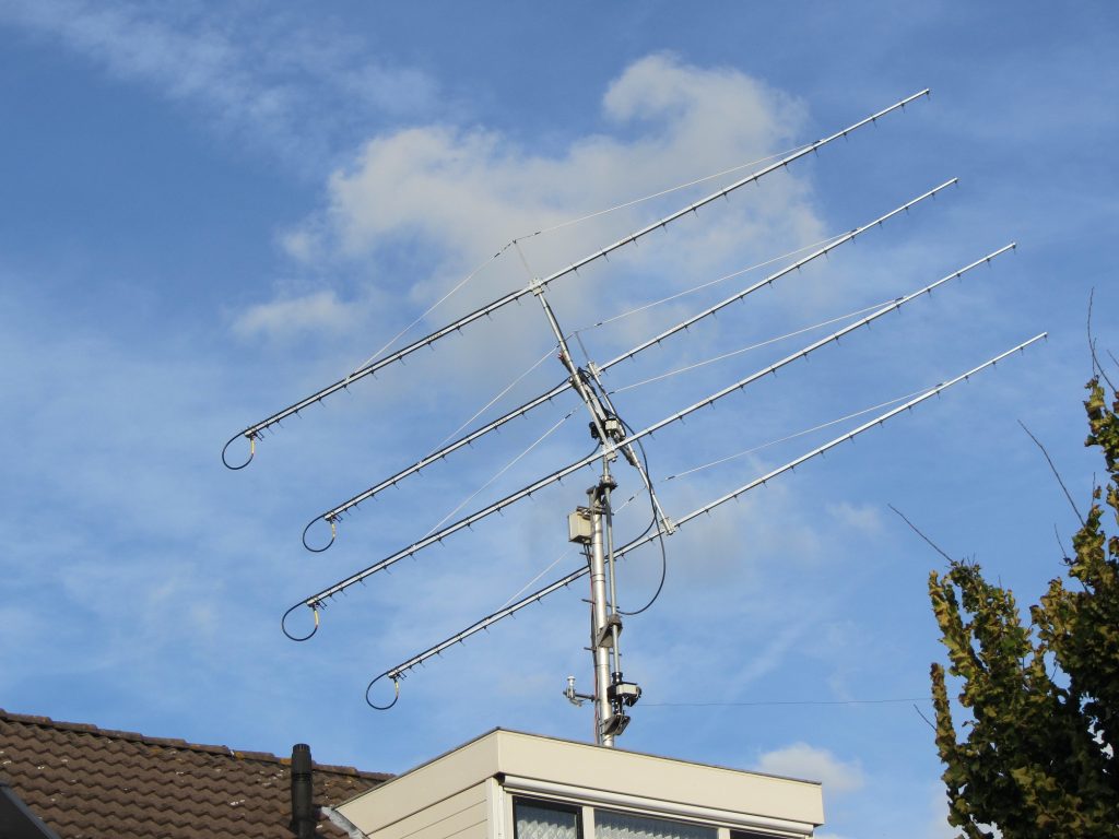
Therefore, you can estimate what you need to buy for the desired antenna construction. Since I will choose the materials in Leroy Merlin, it is necessary to proceed from what is available in the shop. For example, an antenna boom can be made of a square tube. Standard lengths are 1, 2, 2.6 meters. Two meters long tubes are more or less ok for transportation. Using a primitive Yagi calculator, you can estimate how many elements will fit within 2 meters of a boom (estimated frequency 408 MHz):
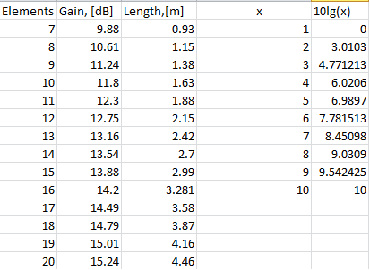
So, if there will be 11 elements (two reflectors, one dipole, and nine directors), the total gain of the antenna will be about 12.3 dB. This gain is not enough for our purpose (the minimum is 14 dB + extra). The additional gain can be obtained by several similar antennas assembled in the in-phase antenna array. The total gain of such an assembly is:
where  is the gain of one antenna and
  is the number of antennas in the array. The decimal logarithm is shown in the table above, so let's say with four two-meter antennas we will have a total gain of 12.3 + 6 = 18.3 dB, which should be sufficient for our purpose.
The manufacture of antenna array requires some knowledge of the principles of their operation. Well, let's look at some of the main ideas.
Theory of the antenna phased array
The total field of the linear phase array (when the phase difference of neighbour antennas is the same):
where  is the single antenna directivity patern in the grid,
  is the distance from the
  -th antenna to the point of observation,
  is the phase difference between the fields of neighbor emitters at a distance
  .
.
Considering that:
Then:
The expression
determines the phase pattern. It is easy to see that for a linear phased array, the phase center coincides with the geometric center.
The experession
determines the amplitude pattern. At  :
:
that is, the total array gain is as many times higher as many single antenna are in the array.
The width of the main lobe of the radiation pattern is:
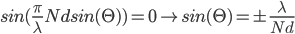
The condition of the existence of only one main lobe, the distance between the antennas must not exceed the wavelength.
According to Rothhammel, the optimal distance between antennas is:
where  is half the width of the single antenna directivity pattern.
Antenna alignment in the array
One of the main problems I see at this stage is the in-phase matching of all the antennas in the array. This problem seems so serious to me that I even thought of coming back to the idea with a single antenna. The problem is that if the signals from each antenna add not in phase, they will simply jam each other. The main "enemies" of good phasing are:
- Boom mounting point. For example, one of the antennas is ahead of the other then the signal from it arrives earlier at the antenna connection point.
- Antenna impedance. If the Z wave impedance at different antennas is different, then the phase of the signal ( or the current I = U / Z) will be different for different antennas. For example, the impedance of a dipole is
 . The difference in impedance can be due to environmental influences (trees, buildings, earth). And if the hight of the mast is less than ten wavelengths, the earth's effect on the antenna impedance will be significant. On the other hand, other antenna elements and mounting elements (boom, mast) can "smooth" the resonance depth. For antennas with high directivity, this problem is more important.
 - Transmission lines adjustment.
Let's look at each of the problems separately.
The first problem is significant. In addition, it should be added that the antenna must remain rigid. It will be interesting to model this case in CST. It seems to me that in this case, the phase center will simply shift, without significant loss of amplification. If so, you can correct the antenna by calibrating it on the Sun or Moon (probably).
On the other hand, if we move one of the antennas in the array on a quarter-wave forward and will make a corresponding quarter-wave delay on the transmission line, it will improve the characteristics of the antenna. This is due to the suppression of radio interference coming from behind the antenna: the interference signal is added from the two antennas in the antiphase.
The second problem is more serious. To reduce this effect, the dielectric materials should be used in the manufacture of masts and other antenna mounts. Commonly used material is fiberglass. You can use plastic or wood. The antenna elements must be secured to the electrically conductive boom through a dielectric insulator.
The center of the element is zero voltage point, but most likely, the direct mounting of elements to the boom will also affect the quality.
The antennas in the grid must be fixed as symmetrically as possible. But the cables are attached by rule from left to left, right to right. That is, if the cable shield goes to the left element, then the center wire to the right, and so in all antennas.
Also, it is required to match each antenna with the transmission line.
The third point is the problem with cables. This is the simplest of the problems because the signal propagation time in the cable is precisely determined by the physical length of the cable itself. The diagram below shows the matching scheme of 4 Yagi antennas.
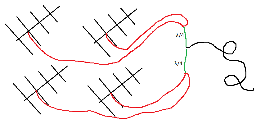
Since the active element is a half-wave dipole, the cable should also be 75 Ohm impedance. Cables from all antennas should be the same length. The receiver should also have a 75 Ohm cable. If we connect two antennas in parallel, we will have 37.5 ohms, if four, then 18.75 ohms. That is, the direct connection of the 75 Ohm cable to this connection will result in significant line losses. A matching element is required to match the line impedances. I will use a quarter-wave transformer.
The quarter-wave transformer works like this. We start with the Transmission line impedance equation (Pozar, Microwave engineering):
we select the length of the line so that  . Divide the denominator and numerator by
  . Then:
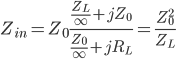
Therefore, the impedance of the matching quarter-wave line must be:
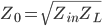
Let's calculate the impedance for a quarter-wave transformer when connecting the antennas as shown in the picture above. At the input of the line, two antennas are connected in parallel, ie the impedance will be 75/2 Ohms. The outputs for the quarter-wave transformers are connected in parallel and run on the 75 Ohm line, so the output impedance of each transformer is 72 * 2 Ohms. The formula above calculates that the impedance of this element should be:
Nice! In addition, this transformer performs certain filtering functions.
Conclusion
I made a quite disappointing discovery for myself with this phase agreement. On the other hand, there are successful, many years of experience in the operation of such antennas arrays, so I think the problems are not really so critical. In any case, there are some solutions:
- Precise mounting of the antenna
- Install the antenna as high as possible and away from obstructions
- Use of dielectric materials for the mast, isolate the elements of the antenna from electrically conductive boom
- Adjust each of the antennas in the grid (hopefully, they will be only 4)
- Modeling of the antenna in CST to obtain the optimal design and to determine the margin of error and to determine the critical elements.
The simulation should also suggest what you can correct on the already made antenna to adjust it. A survey of EME antenna designs shows that things are not so bad. However, I still ask myself whether it should be built at all, taking into account the error of phase? And can we use a delay line for phase correction? Can phase error be corrected using the Sun or the Moon (something like calibration)?