
As any creative project have the turns in the wrong way, the same happens to me when I had considered an in-phase antenna array. The problem of this antenna is not only in matching but also in high mechanical complexity. The mechanical structure should be made from dielectric material. If I would be in my farm in Ukraine, I would construct it from wood, but in a small studio in Nice, this antenna array would definitely not fits and it would be too difficult to transport it.
Basically, a single well-adjusted antenna of less than 3m length would have a gain of 14 dB or even more (at 70 cm wavelength). The length of 3 meters is not a lot for antenna, but it would be much easier and much cheaper
to make.
As I probably confuse the reader with my previous note, I would remind that our goal is to build an antenna at 406-410 MHz frequency range (range of radio astronomical observations) with gain at least 14 dB and with low noise (temperature) as possible. It would be good to have an antenna with high directivity and small sidelobes (through which it can catch the noise). I should empathize that exact frequency doesn't matter because the signal which we are going to receive is wideband. As we are going to limit the receiving bandwidth on 1 MHz, so we don't need a high bandwidth antenna due to noise reasons as well.
Before we start the manufacturing of the antenna, I would like to simulate and optimize it first. Also, I need to adjust antenna dimensions in accordance with available in Leroy Merlin aluminum profiles (tubes, rods, etc). To reduce the computation time, we need to find the first approach of antenna dimensions. For this, I had used an online Yagi antenna calculator (basically its table with parameters from Rothammel). This dimension I put into the CST model and start the calculations. However, the result was far from expected. The next attempts to optimize took too much time and was inefficient.
The solution came with time. I thought: there are many antennas on amateur frequency 430 MHz. They are well optimized and many of these designs were implemented in life. Why not take one of these designs and scale it down in wavelength? As the wavelengths would be close, so the nonlinear parameters would not much matter. I had tried 2 antennas of yu7ef.com. This antennas are EF7012 and EF7013. They were designed in TANN. CST model provides somehow different results. I trust more to CST model. As a result, design EF1012 is slightly better.
The model in CST looks like this:
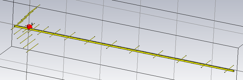
I made two improvements of the design: I add reflector grid and 11th director (EF7012 have only 12 elements and initially I thought to use the solid tube from Leroy Merlin on 2.6m)
I perform the simulation taking into account what I can buy in the shop. However, when I arrive in the biggest construction shop in the area I didn't find what I need and I made some corrections to the model again. For example, I thought to use aluminum rods for the elements of the antenna, however, I didn't find them available, so I switch to tubes of equivalent diameter. The tube for the boom which I was initially thought to use was too long for any convenient transportation. So I took 3 of 1m long tubes and connect them together. So antenna became 40 cm longer from the initial design and that's why I add one more element (director).
Except for CST, I model also in 4nec2. It's not difficult to learn how to make simulation in this software. I find a few good "tutorials" for nec and CST. Some other popular software for antenna simulation are ANSYS and MMANA-GAL.
But before presenting the results of the simulation, I would like to introduce some antenna theory. See you on the next note 😉