
In the case of artificial radio interference (Radio Frequency Interference), the external filter is a necessary part of the radiotelescope.
Let's start with the basics. In the simplified case, the bandpass filter has two parameters: main frequency and bandwidth. The bandwidth is measured at -3dB, ie when the signal is twice weaker. The frequency in our case is equal to the frequency of the antenna, and the bandwidth is limited from the floor 2 MHz (~ maximum bandwidth of the RTL-SDR receiver). A small bandwidth requires handling small capacities and inductors, which is difficult because the parasitic parameters of the components in the filter begin to play a significant role. So I increased the bandwidth to 15MHz in the hope that someday I will change the RTL-SDR in a more advanced receiver.
Another parameter (not less important) is the input and output impedance (50 Ohms). The next step is to select the filter type. Honestly, I didn't bother with studying all types of filters, their advantages, and disadvantages. I watched the video and recalculate the parameters for my needs. I did the filter calculation with this program. This type of filter is the most popular - bipolar Direct coupled.
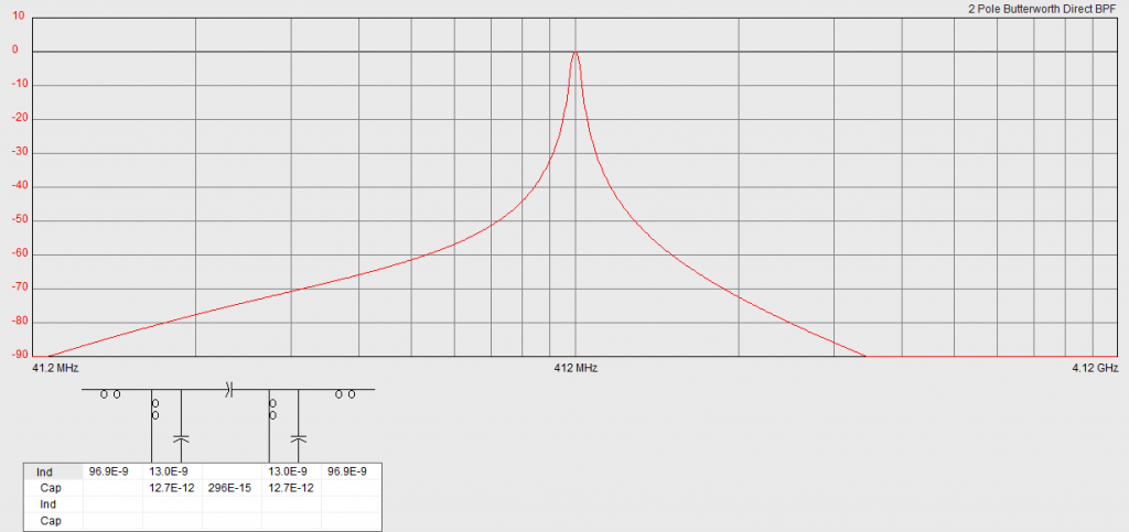
Input and output are inductors (can be changed to capacitance). The inductance cuts at high frequencies by 20 dB (at least) better than the capacitance. At first view, the values of the components may be confusing: where will I find such custom components? Actually, all the components, except for the two trimmer capacitors, are self-made. Inductance - Homemade coils. They can be calculated in any online calculator. A capacitor in the middle has a capacity of a quarter of a picofarad. This is far from being a standard value. The solution is a gimmick cap. Basically, this is two twisted wires. They can be twisted and unwound, thereby adjusting the capacity. This is a critical element because the impedance of the filter depends on it. The well between the filter links serves for RF isolation.
The filter measurement results (with NanoVNA) are shown in the figures below. Before measuring, the analyzer must be calibrated with the cables coming to the filter.
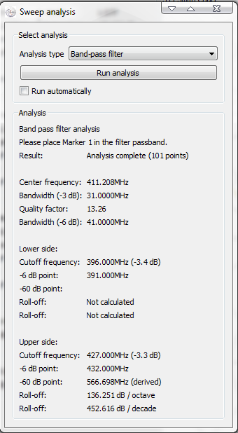
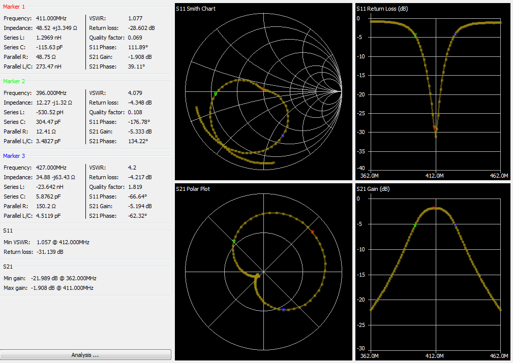
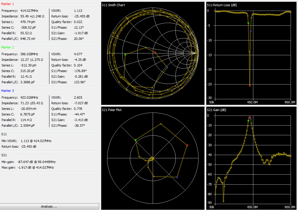
The losses are less than 2 dB -- it's cool!