At the beginning of 2016, I had built my first muon telescope. It has only two counters. This time I'm going to build a new setup, however, the electronics remains almost the same. So let's get started!
Section 0. Physics
IMHO, the muon telescope is a very interesting demonstration setup. The story begins in the 1930s. The muon was discovered by Anderson in 1936, while he was studying cosmic rays. He was a brilliant scientist. The same year he got a Nobel prize for positron discovery. In the beginning, there was confusion about muon, because people thought that this particle is responsible for strong interaction (you can look for this story in Perkins). But basically, muon is a kind of electron, but much more heavy and unstable particle. His lifetime is about 2.2 microseconds. It's nothing for us, but it's an eternity for particles. But how to detect a muon, if it lives so short time? With the coincidence circuit! It activates only if both inputs receive the signal at the same time (in some time window). The idea is so simple, that it is genius. For this, in 1954 Walther Bothe got a Nobel prize. Using this circuit, another Nobel laureate -- Alvarez made a search for hidden chambers in the Egyptian pyramids. However, he got a Nobel prize, not for this.

In this setup, I use as well a coincidence circuit to detect muons. But where I would get muons for my experiment? Same as, as in the 1930s, the source will be cosmic rays. Most of the particles (90 percent or more) which arrived at Each are high-energy protons. They interact with the nucleus of molecules of the Earth's atmosphere (N2, O2 mainly) and create the avalanche of nuclear reactions. This interaction happens at about 30 km high. A zoo of new particles is born. Many of them are unstable. The first is the list is pion. These particles are responsible for the strong interaction. It is with these particles people made confusion in the 1930s about muon nature. But these particles have a very short lifetime (26 nanoseconds). They propagate quite fast (almost with the speed of light), but anyway can not reach the Earth's surface. To detect them, people took their detectors (at that time it was photographic emulsion), put on the balloon, and go high in the sky, closer to the primary interaction point. That how pion was discovered. For the method and the discovery, Cecil Powell got a Nobel prize in 1950. Coming back to our avalanche: pions are unstable and decay into muons! And these muons we detect with our detector.
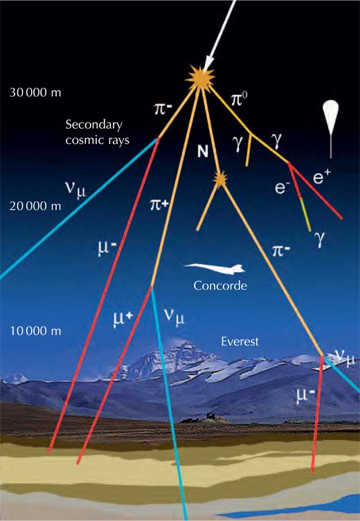
The curious reader may notice that it is multiple muon lifetime on the speed of light we get about 660 meters of distance that they can pass. How they can reach the Earth if the interaction takes place at about 15 km? Actually, it is a classical example of Lorentz transformation. Muon travel with almost speed of light, so time in our frame of reference goes longer than in the frame of reference linked with a muon. In his own frame of reference, he lives 2.2 microseconds, but in our frame of reference, he lives much longer.
Using the fact that it is a high-energy particle, it can pass throw two detectors at about the same time. It is almost impossible for electrons in natural nuclear reactions, which happen around us (energies are low). So we can be sure, that if at the same time, two detectors have a signal, it is the same particle pass throw two of them and this particle is a muon.
More of this, we can check the distribution of the muons. The shortest distance to the 15 km altitude is strictly vertical (A on the picture below). So muon needs to pass the shortest distance. The reactions happen all around the sky (blue line). So if we will look at some point C (see fig below) at the sky, we will also see that muons birth there, and some of them travel to our detector (B on the figure). It is obvious that distance AB is shorter than CB. The feature of the muon that it is an unstable particle. Mote distance it travels, the higher probability that it would decay. If more of them would decay, so less of them we will detect.
Two detectors' orientation defines the detection direction. So if we change this orientation, we would detect the muons, which arrive from other direction, and so we expect to see fewer and fewer muons when we change the orientation of detectors from vertical to horizontal.
Last but not least, the question is why it is called a telescope? here is no optics! In science, almost all the staff, which looks in the sky is called a telescope.
Section 1. The frame
The telescope has a simple cylindrical geometry. In the center is a Geiger counter. The same counters (detector) are placed on the circle with a radius of 30 cm with a separation angle of 30 deg (at 30, 60, 90, 120, 150 deg). For perfection, two counters at horizontal are missed. But I had bought only a limited number of them. All the components are printed on my 3D printer. All the models are here. All the connections are on screws. For this, I melt in in plastic special threaded insert. I did not make gluing, at I hate it. The base of the telescope is a thin aluminum plate. Unter It I had mounted the small gum legs.
Honestly, the connection and contact of Geiger counters are not the best. Sometimes the arcs move and the contact is lost. I would suggest using fuse holders for PCB to make a detector connection. In this version, I had used copper tape to make the contacts. The tape I insert in the holes of the arc frame and solder wire to this tape.
Under each of the counter, I put a LED to indicate the direction of detection.
Section 2. Electronics
The schemas are here and here.
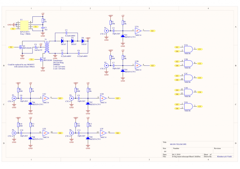
The generator and pulse shaper is the same as in the previous version of the circuit. The real upgrade is only the powering from 5 V (from USB). Also, I should mention the resistor, which pull-up the Zener diode on the input of the Schmitt trigger. Basically, this resistor sets the level of detection. I case of significant cross-talk, the value of the resistor should be chosen carefully. Actually, the problem of cross-talk is one of the most significant problems in this setup. In the process of development, I had to waste a significant amount of time (about a quarter of all time) to solve it. I'm not 100% sure that it disappears completely, but is significantly eliminated.
The other part is logic and display.
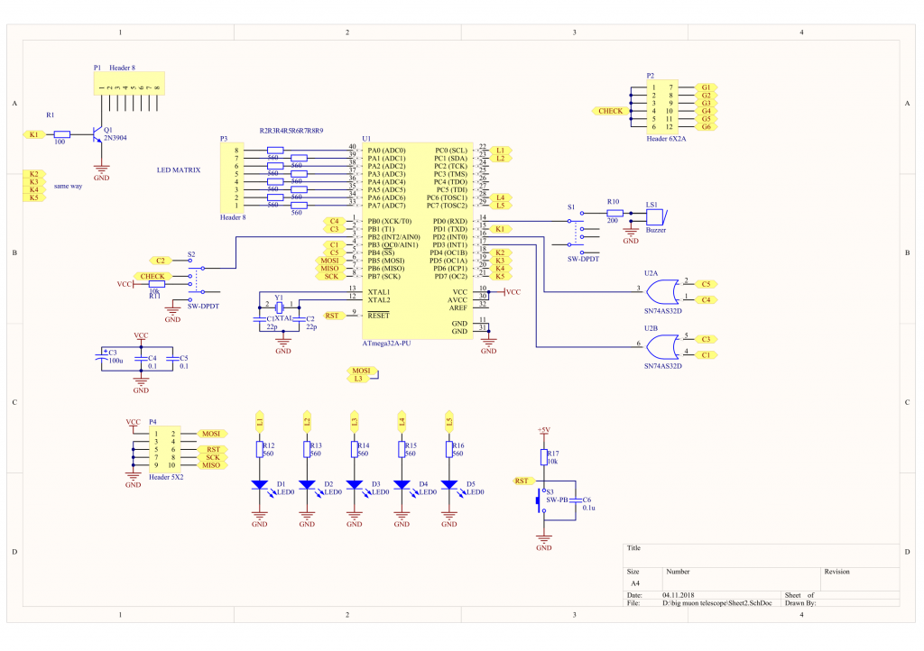
ATmega32A is in charge of this. I don't need so much memory of MCU, but I need a lot of legs. It would be nice to have an interrupt for each coincidence circuit. But the MCU has only 3 of them, so I need to insert an OR chip. to detect well the signal from 5 coincidence circuits. Plus, the signal from it is short, I stray-way solution doesn't work. It not difficult to stretch the signals of some logic chip, but I didn't want to overcomplicate the device. I rewrite the Interrupt service routine and it starts to react faster.
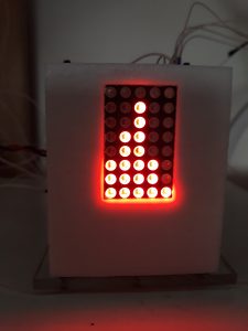
When the MCU detects the coincidence, it makes "piuuu" with buzzer, blinks with LED on the arc, adds +1 to the corresponding column of the histogram, and shows it on the LED matrix. The program of MCU is here. If you will repeat, don't forget to set fuses on 16 MHz.
All the electronics are assembled in the étagère of three levels: the first is the HV generator and all high voltage staff, the second is pulse shaper and coincidence circuit, the third is MCU with the interface. Also, the second level has a connector to check each of the counters separately.
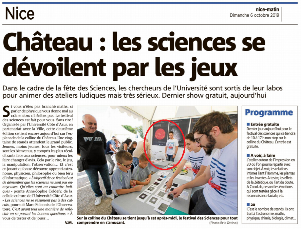
This project took a lot of time to make, but I'm happy that I did it. This is my main project for autumn 2018. I had presented it on Fête de la Science in Nice in 2018 and 2019.
