
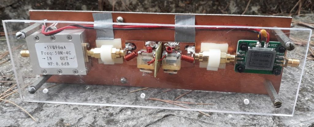
So all the components of the radio telescope are ready and its time to assemble them together and try them in practice. The first version of the amplification/filtering module is in the picture below:
Here I will tell you about the first but wrong configuration. Anyway, a bad experience is also an experience, and I hope you will not repeat my mistakes. In the first version, I connect the antenna to the preamp throw a short cable (RG-58 50 Ohm). The cable is about one wavelength long (taking into account the shortening 0.66 coefficient). A good practice is to check the cables and to don't trust the Chinese cables. To make the cables for my telescope I bought an instrument to jam them. It is not difficult to make cable by yourself and it is cheaper as well.
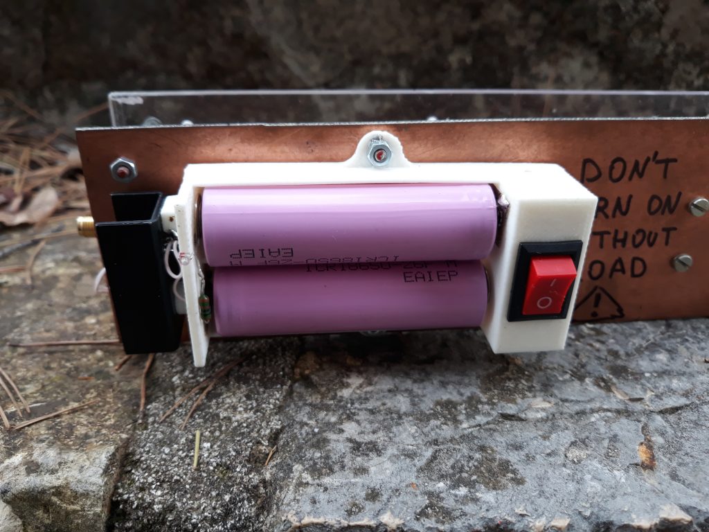
The receiver's amplifier of the radio telescope should have small noise (should be LNA). I had talked about how to measure the noise in a few notes before. For my radio telescope, I bought a Chinese LNA. There are few low-cost LNA in the market. I choose one on spf5189z. The first from the antenna stays LNA with a metal package and a filter on the powerline. This is the most critical chain in electronics of the radiotelescope. The noise of this amplifier will be amplified by himself and other amplifiers and so it will reduce the "efficiency" of the whole system. The next chain is RF filter which I made last time and other LNA amplifiers with the same chip. I don't know if there is a significant difference between these two amplifiers. That parameters which I can measure with NanoVNA are rather a difference between two chips in series rather than PCB or filter or shielding effect. For power, I use 2 Li-ion batteries 18650 and 7805 linear voltage regulator. The powering solutions based on switching circuits are not acceptable in this situation.
After LNAs and filters, the signal goes to the SDR receiver. First I thought to use a short cable to connect last LNA to SDR and then use a USB cable, but on it doesn't work (some problem in fast transmission with 3m long shielded USB cable). So the solution was to connect the amplifier to SDR throw 2m coaxial cable and the SDR receiver to the port of the computer.
For the planning of the observation and estimate of efficiency, I had used the MURMUR program.
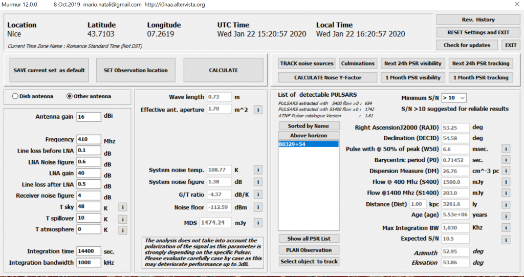
As soon I set the observation position, I can calculate which astro-objects I can see, in which direction to point the telescope (azimuth, elevation) and etc. Quite useful is a test of the telescope by natural radio noise sources (Sun, Moon, stars) but I didn't try it.
Unfortunately, the pointing was a weak point of my radiotelescope. For pointing, I use a compass application on my mobile phone on azimuth and improvised astrolyabia on elevation. However, the main lobe of the antenna have 30 deg, so I don't need extra precision.
The next step is configuring the programs on PC to acquire the data. If you have virgin Ubuntu (just after installation), you should not have problems.
You should install gnuradio and osmosdr:
sudo apt install gnuradio
sudo apt-get install -y gr-osmosdr
To take and channelize the data from RTL-SDR I use python script of IW5BHY. The corrected version of it I live here.
To start the record, you should set few recording parameters: time of record in seconds, the sample rate in sps; receiving frequency in MHz; amplification RF in dB, amplification BB (0 for RTL-SDR), amplification IF (0 for RTL-SDR); fftsize (sps), decimation; digital amplification; the name of the output file.
You should tune the amplification to get that power spectrum as in the picture below:
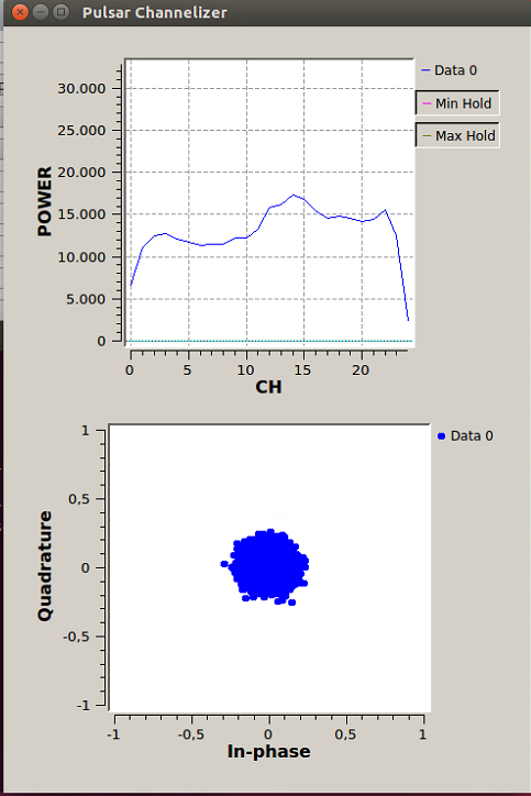
There are two other parameters: Sample rate of time series (2ksps will be ok). Using this, we can calculate:
fft size = sample rate / Sample rate of time series
The number of channels (num chan) of 25 is also ok, so:
Decimation = fft size / num chan
To start the script:
sudo python2 PulsChan.py 3600 2400000 413 15 0 0 1200 48 2 B0329+54.bin
If it doesn't work, you should check your receiver. (in gqrx for example). gqrx is kind of SDR# for linux. To install :
sudo apt-get install gqrx-sdr
The radiotelescope in the working mode is shown at the top of the note. The holder of the mast is part of the old sun umbrella (very Cote d'Azur solution 🙂 ). After the record is finished, you will need to analyze the data. I had used this instruction and their prepared ubuntu distribution (thanks a lot for them!).
My first attempt is unsuccessful because I wanted to use their ubuntu distributive to record data as well. But when I had installed the antenna, I realize that the SRD receiver doesn't work from a computer battery with this version of ubuntu in a live mode (some bug).
The result of the second attempt:
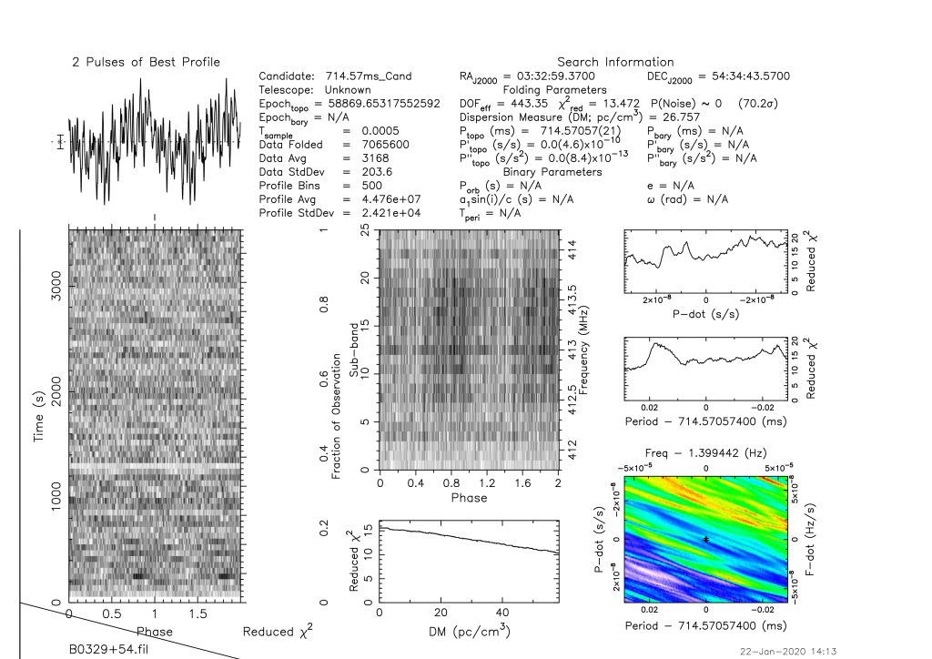
Nothing. The data was significantly cutter by the RFI filter so I will try in the other place and I will increase the receiving time.